


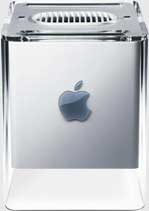
  Introduced July 19, 2000, discontinued July 3, 2001 Introduced July 19, 2000, discontinued July 3, 2001Launched at MacWorld Expo in San Francisco, the brand-new Cube was displayed within a plexiglass tube with its 7-inch cube core suspended just above its inverted case. Looking more like some sort of satellite than a computer, the G4 PowerMac Cube boasted a 450MHz PowerPC G4 processor, a 20, 40 or 60 GB IDE/PATA hard drive (maximum drive capacity = 128GB), and three RAM slots for up to 1.5GB RAM. It also shipped with a Combo DVD-ROM/CD-RW drive (addressed below).
Code named "Trinity," the G4 Cube was initially priced at $1799, dropped to $1299 seven months later. There was also a 500MHz BTO version available direct from Apple for $2299. Sales were rather disappointing (150,000 units), and the Power Mac Cube was put on "indefinite hold" (discontinued) after only a year. Some have suggested the Mac Cube evolved from NeXT Computer and the $10,000 magnesium-case NeXTcube when Steve Jobs returned to Apple after being ousted in 1985. Next merged with Apple in 1997. Power is provided by an external 205-watt power supply, 110/240v AC input @ 50/60Hz, output = 28v @ 8.125A, model M5949. Video output from the Cube's stock ATI Rage 128 GPU supports up 1920 x 1200 pixels in 32-bit color thru conventional VGA or via Apple's proprietary ADC port which combines power with analog/digital DVI output plus USB in a single cable. Both the Cube and its power supply operate in near-perfect silence since neither one had a fan. 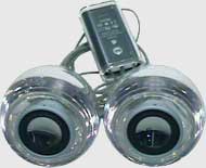 Apple's matching acrylic Studio Displays came in 15, 17 and 20-inch configurations, each equipped with an extra pair of USB ports. Although the Cube itself had no audio capability (the only Mac ever without audio), 4-inch diameter acrylic stereo speakers were available (left), powered thru USB from the Cube or one of its Studio Display ports. IMPORTANT OS NOTE: The last native MacOS that a G4 Cube can run is Tiger version 10.4.11, which runs well on the Cube - except that under 10.4.11 the Cube's optical drive is not recognized. There might well be a workaround for the OD problem, possibly a firmware update (v4.1.9 is last), but the shop Cube has been happily running iTunes 7 under Panther OS 10.3.9 all day, every day - so Panther is where it will stay. Freshly restored optical drive in action:
Before opening a Cube...
If restoring a G4 Cube is on your to-do list, downloading a copy of machine's service manual first thing is highly recommended. It is a 3.8MB PDF document that can be found on the internet from a variety of sources; search for "Power Mac G4 Cube M7886 manual" and pick a safe source or look on eBay, typically $10 or less and money well spent. Other identifiers: Power Mac G4 (5,1) model M7886, EMC# 1844, order# M7642LL/A.
Keep in mind that these machines date back to Y2K and some of its parts and connectors may be stuck in place after all these years. To make matters worse, plastic parts tend to become more fragile with age. Use special care when disconnecting cables, removing RAM, and unplugging things for the first time. The ADC video connector in particular has always been a concern, as it is far too easy to bend pins and do damage. Other connectors might actually require some force to pry loose (the 4-pin power plug to hard drive, for example); just be careful. Use a shot of WD-40 if you have to. Once apart, a very light application of dielectric grease to pins and connectors will prevent them from welding themselves together again. The OD eject mechanism is a belt drive, guaranteed to be slipping after all these years and the reason why CDs won't eject. If you can find replacement belts, do yourself a favor and install two of 'em. ;-)
|

Servicing
this power supply is a complete PITA and cannot be done without some cosmetic damage to outer case and breaking clips due to age. If your PS doesn't work, there's nothing to lose - otherwise, it's best left alone.
 Opening the outer case Opening the outer caseEach end cover snaps into metal inner case with a clip at each end, as shown (right). Note locating pin next to clip; this effectively eliminates any hope of removing end covers without damaging at least one clip. It might be possible to push clip inward once a pry tool gets under end cap - but not likely. Brute force may be required. Keeping cosmetic damage to a minimum is about the best you can hope for.
Once end caps are pried off, outer cover will slide free. Remove four screws, two on each side of inner metal housing. Next, pry metal housing open along one edge or the other (both are fastened in the same way) by freeing three clips on each side. 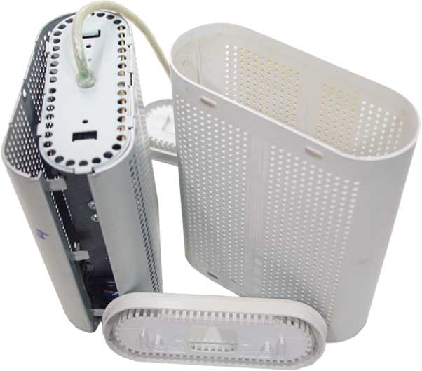 Removing shields for inspection
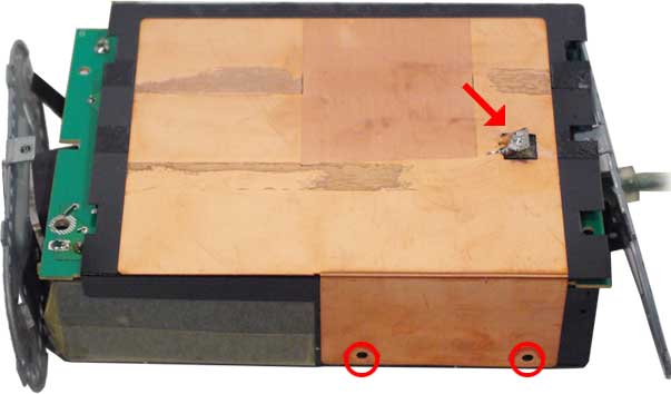
A soldering iron is required to remove two shields, starting with the outer copper cover below (shield 1). Remove two screws (red circles) then desolder wire from raised copper tab (red arrow).
 Lifting outer shield #1 reveals a second shield #2 (below) which is also soldered to PCB in two locations (at red arrows). Remove solder connections and remove shield #2, noting its location relative to circuit board and to outer copper shield.
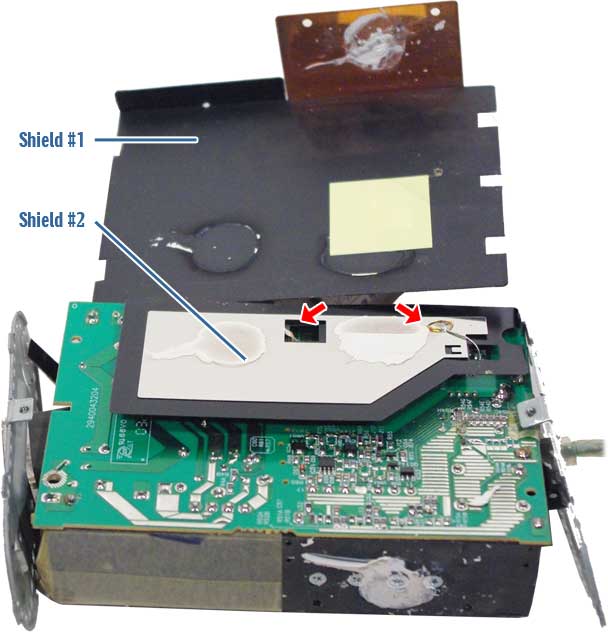 Removing these shields will allow examination of printed circuit board. Look for discoloration from heat, fried components and damaged traces.
To examine component side of power supply, you will have to remove a fair amount of plastic wrapping, tape, rubber pads and caps, plus yet another shield, (below). 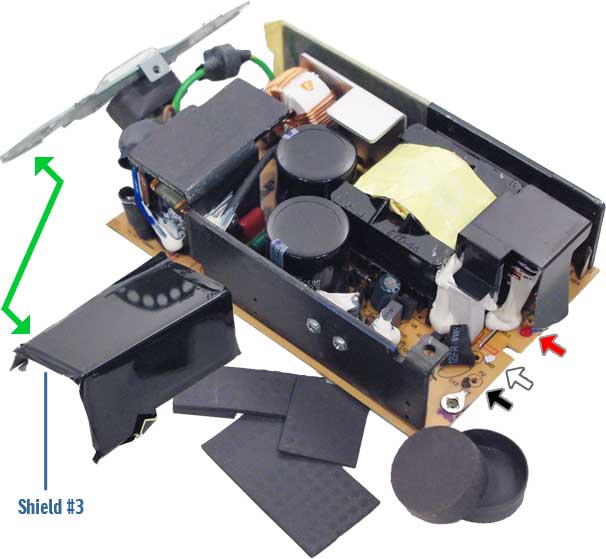 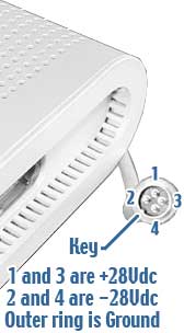 AC power cord was also removed from near end of board, marked by black, white and red dots along edge, tho this step may not be necessary. Another shield (#3) is shown above - this one slides under matching bracket, and has a tab that grounds to bare metal on end of inner housing (green arrow). A plastic liner (not shown) also helps insulate components inside metal housing. AC power cord was also removed from near end of board, marked by black, white and red dots along edge, tho this step may not be necessary. Another shield (#3) is shown above - this one slides under matching bracket, and has a tab that grounds to bare metal on end of inner housing (green arrow). A plastic liner (not shown) also helps insulate components inside metal housing.Examine components for signs of damage or discoloration, check capacitors for swelling or leaking, check mounts and connections, and check fuse (near AC-in) for continuity (Fuse is glass-tube type, soldered vertically and covered with shrink wrap for your convenience.) Blow out any dust. This unit showed no damage, but was not operating properly. After a good cleaning and careful reassembly, it was back in service. Reassemble Power Supply and test
You may choose to put rubber pads (shown above) back in place, and to re-wrap cables and tape components if you wish - or not. We opted to omit pads and tape where insulation was not required in favor of
better cooling and ventilation.
Start by tucking small shield (#3, above) under bracket where it belongs, then replace and re-solder power cables and ground screw (if removed). Go back thru disassembly steps in reverse order: Put shield #2 back in place and re-solder ground wires, then do the same for shield #1 on top of it, replacing the two phillips screws. Fit top and bottom halves of metal housing together, then fit both ends of metal housing to unit, making sure tab on shield #3 mates with bare metal on end cap. Note two tiny slits in center of top metal housing that mate with two matching tabs inside plastic cover, snap housing halves back together over end caps. Install 4 phillips screws, 2 at each end, then slide outer plastic cover back in place with its two tiny tabs fitting into slots at top-center of unit. You may wish to test power supply operation and output before snapping end covers in place. |

Optical
drives of this vintage are notorious for having various age-related issues, first of which being its belt-drive mechanism. Popular back in the 8-track and cassette tape days, rubber belt drives are prone to fail when rubber stretches and hardens, losing traction. In the case of this particular device, there is also a rubber roller that fails; between the two, these drives lose their ability to eject, especially since they must lift the disc vertically.
Other issues have to do with IDE/PATA devices that utilized "master-slave" configuration, as well as the connectors used on these devices (covered below). Remove cover's two tiny screws on each side at front and slide cover from slots at rear, revealing a very busy drive mechanism. It's a wonder these things worked at all, and coaxing one back to life after 20 years is no small feat. 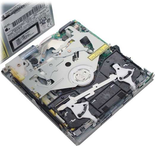 Drive belt can be seen on left side with slot opening facing forward. Capstan is dead-center and will easily fall out of its bracket.
Addressing belt drive and roller issue
Only solution for the belt is to replace it with a new one, but the roller mechanism can be repaired. Start by slipping old belt off its track. Original belts were stout and should measure about 2.5" in diameter (roughly). Vendors on eBay sell assortments of belts in various sizes, and the last batch we bought had six of proper size - but they are much thinner than the original drive belt was. Solution is to double-up new belts - BUT - don't install belt(s) yet, they go on with last step. I suppose a belt might be cut from an inner tube, in a pinch - maybe. New belts are shown below, next to worn-out OEM belt.
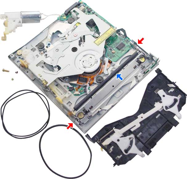 Remove forward (black/white plastic) disc guide assembly by releasing two tiny springs (at red arrows), then lift assembly off its hinges and set aside, exposing rubber roller beneath (blue arrow). This roller consists of two rubber sleeves that taper to the center of the steel shaft they ride on. Aged rubber sleeves commonly spin free on roller shaft, providing zero lift. We gonna fix dat.
One end of shaft (left end in pic above) is driven by the belt and has a plastic pulley and bracket pressed onto it. This tiny plastic bracket snaps into a retaining slot. Remove the shaft by gently prying its pulley/bracket out of end slot, being careful not to lose a wee-tiny non-metallic washer on shaft's other (right) end. Slide rubber sleeves off of steel roller shaft. Solution here is to fit a small-diameter piece of shrinkwrap over shaft, shrink to fit and trim (being careful not to melt plastic pulley/bracket), then slide rubber sleeves back onto shaft over shrinkwrap (which may require a little spit-lube ;-). Remember to fit tapers to center, and stretch sleeves as necessary to center them, leaving about 1/8" at each end (as shown above). Refit micro washer to shaft, install washer end of roller shaft, then the snap plastic pulley/bracket end back into its slot. Replace forward (black/white plastic) disc guide assembly by pivoting it back into hinges and reattaching the two tiny springs (at red arrows). BTW: Rear metal disc guide assembly may also be removed by releasing its two tiny springs and pivoting assembly up and off of hinges. Under this assembly lies the laser and its motorized track, but this is best left alone unless cleaning/lube is required. Reassembling optical drive
Best way to reassemble device is to remove motor/gear assembly at rear of drive by removing three phillips screws (shown below): Big screw from center of gear bracket, medium screw in corner of drive, small screw under rear pulley. Move motor aside.
Insert a CD or DVD into drive. A few things will need attention: The forward black/white disc guide has four white plastic pins that move aside on insertion, two up-top and a pair hidden underneath to rear of guide. These two rear ones must spread to either side or disc will not seat properly. Next is capstan which needs to be right-side-up and in its slot. Finally, a white plastic arm in back of drive (under rear metal guide, blue arrow, below) should catch edge of disk and be pushed rearward. This last arm interacts with a plastic slider on left side of drive, inboard from belt pulleys. DON'T FORCE ANYTHING! 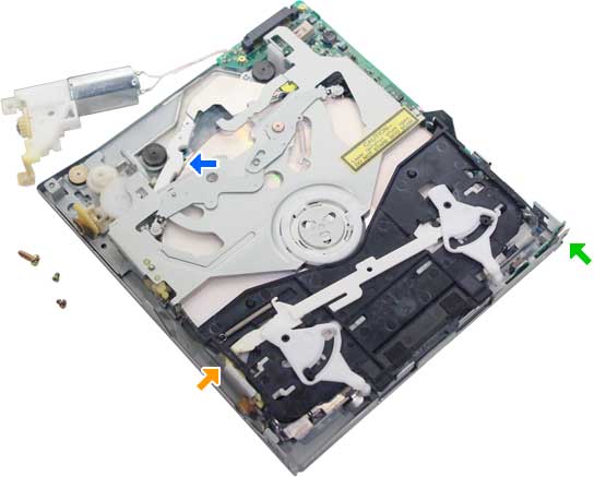 With motor out of the way, try gently pushing the tan plastic slider (orange arrow) forward or rearward until capstan snaps down onto motor magnets in center of drive. When all is correct, both forward plastic guide and rear metal guide will be down flat on disc, as shown above, with disc in place. If not, keep (gently) tinkering with it until guides and capstan are all properly positioned.
Leave CD/DVD in place for the duration and reinstall motor/gear assembly with its three screws. Place belt(s) onto pulleys making sure there are no snags, and - finally(!) - install drive's cover by sliding three tabs into rear slots and replacing two tiny screws at front sides. When drive is powered on, it should eject the disc automatically; if not, use a pointed instrument to press drive's eject switch, front right end of slot (green arrow). Newer ATAPI optical drives, mount and master/slave considerations
While replacing the old belt-powered disc drive with a newer one is a very good (and obvious) idea, this presents a number of terminal problems that might not be readily apparent.
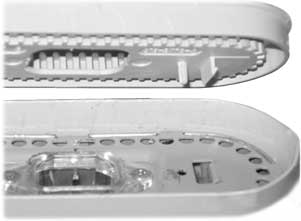
First off, the Cube's original OD has an ATAPI connector (shown below) which is upside-down from every ATAPI port that has since come after it. When plugged into a newer drive, the Cube's connection board (part# 820-1130-A) extends in the wrong direction, off to side of drive instead of mounting directly behind it: 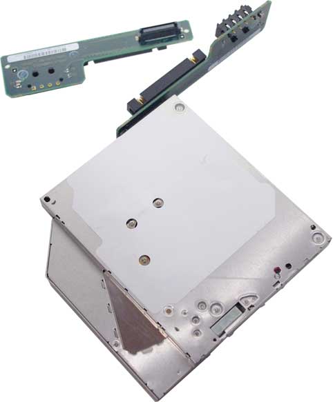 A newer ATAPI optical drive like the one shown above, will work correctly when connected to an up-and-running G4 Cube, using the Cube's original connector upside-down, as shown. It's even properly identified in the Cube's System Profile. Another problem: Later drives are all hard-wired "master" and will prevent startup.
Possible workaround is to set internal HDD to "slave" ("cable-select" does not work), but there's still the inverted connector making installation all but impossible, especially since drive must align with slot in Cube's outer case. Perhaps somebody out there has a solution, but best choice here was to refurb the old OEM drive.  |

|
Adding a fan
Although the Cube has survived all these years without one (thanks to Steve Jobs), adding a fan can't hurt and is a way-cool super-nerdy thing to do. The fact that the Cube already has brackets and power available for a fan makes it an easy mod.
Thickness of fan determines length of mount screws, as mounts are less than 10mm from bottom of frame. We installed 15mm-thick fans in both Cubes using screws that measured 20mm in length. (A 20mm-thick fan would require 25mm screws.) Silent operation is most important in the long run, so select a quality fan for this project. Our first 15mm fan model installed ages ago was a "Global WIN" brand ball fan which has been perfect all these years; second 15mm fan is an ADDA brand "Hypro bearing" 12v fan which is also whisper quiet.
It will be necessary to remove HDD, video card and riser, DC-DC board, modem, CPU and logic board to access fan mounts. Optical drive can remain in place, just be sure its cables do not get trapped in fan mounts.
Looking down from top of Cube, two mount screws are accessible thru HDD bay (circled in red) while the other two are next to central heatsink (next pic). Fan should draw air from under machine and push air upward to assist cooling by convection. Orange arrow (below) marks direction of wires from fan corner to DC-DC board. 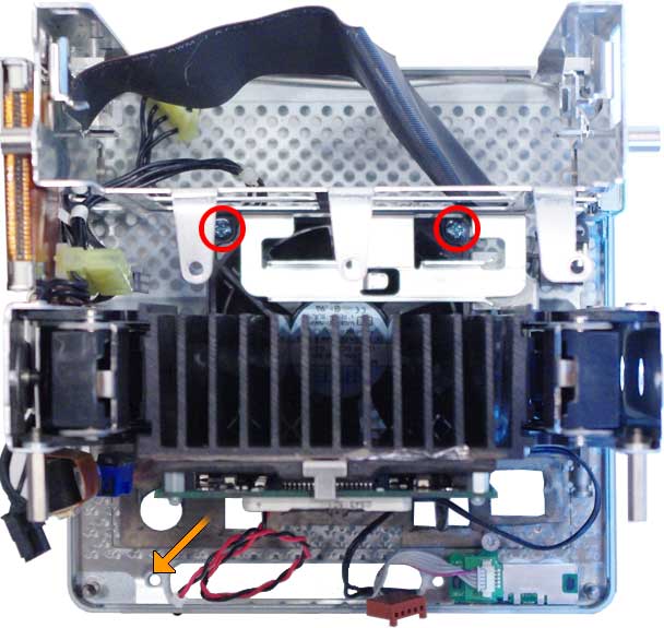 From logic board side of Cube (below), the other two fan mount screws can be seen next to central heatsink (red circles). Closeup of plug/socket arrangement shows connector used to power fan; these connectors are quite common, often used as battery connectors within small rechargeable devices. They are available on eBay. Socket located on corner of DC-DC board provides 12v DC. Check/confirm voltage and polarity, (+) out should be closest to corner of board. 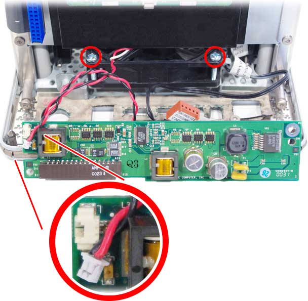 Reassembly tips
With fan in place and secured, reinstall logic board/CPU assembly to central heatsink, connect ATA and Airport cables under logic board, make sure 3 spacers are properly seated between CPU and logic board, install 3 spring-loaded screws to heatsink (short/gold one in center), install ethernet card, modem and six other mounts.
Route fan wires from corner nearest power-in port, around logic board and behind support bar to DC-DC board location. Install DC-DC board by connecting fan cable first, angle DC-DC board into logic board connector and snap into place, then (last) connect black 4-pin power cable. Next, install graphics card, keeping fan wires out of the way of mounts. Tuck-in fan wires to avoid pinching 'em when sliding core into outer case. Install corner support bars, HDD and top plate, then power-up Cube core and check fan operation before placing core back into outer case. Reset clock and you're done! |

|
Replacing USB ports
The Cube only has two USB ports onboard: One gets keyboard/mouse, and the other is used by a printer or - in our case - external audio. These are the only USB ports available, unless using an Apple ADC-connected display which adds two more. In any case, those USB ports are petty important and well worth replacing a worn out or damaged connector.
Disassemble Cube to logic board, remove and strip logic board (incl. ethernet card that appears still attached in image below).
WARNING: Be advised, you risk destroying logic board in the process of making component-level repairs like the port replacement project described here. Requires soldering skills and some knowledge of electronic components.  First, remove screw securing ground lug to get it out of the way and clear of solder points. Original USB ports must be un-soldered and removed; this requires copper braid and/or suction to remove old solder as quickly as possible to avoid damage to other components. No easy way to do this; a mistake here could destroy logic board. You could try replacing one port only, but might as well replace both, no? Use a tiny drill bit to safely open-up the 12 PCB mounting holes if necessary (8 connectors + 4 mounts). NOTE: USB-A ports are standardized, so replacements should be an exact match. Fit new ports to logic board and check fit thru housing before soldering if there is any question (tho this should not be necessary). 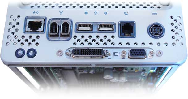 Reassemble and test
 USB ports can get worn out over the years, and may get damaged along the way. Replacing worn/damaged ports does not guarantee a working USB bus, but it's certainly worth the effort. Drawing (left) shows standard USB-A output: 5v DC with center connectors used for data transmission (USB v1.1). USB ports can get worn out over the years, and may get damaged along the way. Replacing worn/damaged ports does not guarantee a working USB bus, but it's certainly worth the effort. Drawing (left) shows standard USB-A output: 5v DC with center connectors used for data transmission (USB v1.1). |

|
Hard Drive upgrade and replacement
Back in the old days, computers used a parallel interface for data transmission and storage, known as PATA, IDE or (originally) simply ATA. An IDE bus can only have two devices attached to it, typically in a master/slave configuration. A third option was soon added known as "cable select" where master device was first device on the 40-pin IDE ribbon cable.
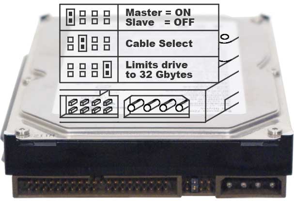 Business end of an IDE hard drive with 40-pin bus, 8-pin jumpers and 4-pin power connector. This drive happens to be the legendary Seagate model ST3120814A 7200rpm 120GB, with its jumper set to Cable Select.
IDE drives usually have a diagram on their label detailing jumper settings, like the drawing above. If not, look up drive model number on manufacturer's web site. Different drive makers used different arrangements, so this diagram is critical.  Western Digital's Jumper settings (from a vintage PATA/IDE hard drive).
The G4 Cube shipped with a 20, 40 or 60GB drive. Maximum drive size the Cube will recognize is 120GB, so this is the drive most often used to upgrade. What happens if a larger drive is installed? Even if partitioned, the drive will show as 120GB total, regardless of actual capacity. This leaves an open-ended partition dangling in space that will eventually cause problems, even if one manages to startup from it. 120GB may seem puny by today's standards, but they were huge back in OS9 days. These drives - while still available - are getting a bit difficult to find. NewEgg has them <http://www.newegg.com> and the following link should take you to 120GB PATA/IDE drives: NewEgg. NewEgg still happens to sell the very same Seagate drive pictured above, current price is $122. |